Variable speed drive energy savings for Fans
The 2# generator (125 MW) operates generally with the load of 70-80%. The flux of two induced draft fans is adjusted by inlet guide vanes. To ensure safe and stable operation of the motor driving the fans, the rated power of the motors is larger than the normal condition. When the generator operates with full load, the inlet guide vanes of the fan is opened about 60%; and when the generator compensates the peak load, the inlet guide vanes of the fans is opened about 40%. So the fan's efficiency is very low and vast energy is wasting in the inlet guide vanes of the fans. The company decided to adopt medium voltage variable speed drives for some fans and pumps to realize saving energy, protecting environment, simplifying the operation and reducing the wearing of rotary equipment, etc. The company has made procurement of medium voltage variable speed drives by the way of international competitive bidding. Gozuk won the contract for 8 units medium voltage variable speed drives.
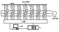
With multi-level cell-connection-in-series technology, medium voltage variable speed drive is composed of phase-shifting transformer, power cell and controller (For the configuration of the 6kV system, see Fig 1). The 6 kV series variable speed drive has 21 power cells and every 7 cells make up a phase in series.
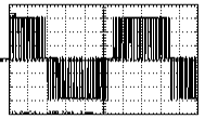
All cells are identical in the structure and electrical parameters of and may be replaced each other. The circuit is basic AC-DC-AC single-phase variable speed drive circuit (See Fig 2). The rectifier is a three-phase diode bridge. Controlling the IGBT inverter by sinusoidal PWM way, the output voltage waveform is shown in fig 3.
Each secondary of the phase shifting transformer supplies power to a power cell. The transformer's secondaries are divided into three groups. For 6000V series, 42 pulses rectifier mode is formed. The multi-pulse overlap rectifier mode greatly improves the quality of the line current waveform, and the input power factor can be improved up to near 1.
In addition, the independence of the transformer's secondaries makes the power cells' main circuit relatively separate. The main circuit of the power cell is similar to the circuit of the low voltage variable speed drive.
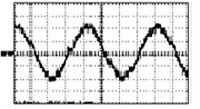
At the output side, each cell's U terminal and the neighbor cell's V terminal are connected in series to form a three phase star (wye) connection to supply power for the motor. By overlapping each cell's PWM waveform, we can get the multi-level SPWM waveform shown in Fig. 4. It is a excellent sine-shape, small dv/dt, no cable and motor insulation destruction, no output filter for long output cable, no motor derating, and it can be used in driving the old motor directly. Meanwhile the motor harmonics are reduced greatly, the mechanical vibration is eliminated, and the mechanical stress of shaft and vanes is reduced.
When one cell fails, this cell may be bypassed off the system through making the soft switch node K in Fig. 2 short and the operation of other cells will not be affected. In this cases, medium voltage variable speed drive operates with derating, the loss resulted from variable speed drive's stop in many cases may be avoided.
The induced draft fans of #2 boiler are configured at both sides. The flux of the induced draft fans is adjusted manually by the inlet guide vanes. Since the designed redundant power of the motor is rather high and the inlet guide vanes used for controlling the air flux cause vast energy loss, the power used by the plant is high and the economic operation of the generator is affected.
In order to fully ensure the system reliability, a bypass device is configured with the variable speed drive. When the medium voltage variable speed drive operates abnormally, it will stop and the motor may be manually switched to be driven directly by the power. The bypass circuit is composed of 3 medium voltage disconnect switches QS1, QS2 and QS3 (see the figure, in which QF is the original medium voltage switch of Party A). It is required that QS2 and QS3 may not be closed simultaneously and they are interlocked mechanically. When the motor is driven by medium voltage variable speed drive, QS1 and QS2 are closed and QS3 is open; and when the motor is driven by the power, QS3 is closed and QS1 and QS2 are open.
In order to protect from medium voltage variable speed drive failure, medium voltage variable speed drive is interlocked with the 6kV switch QF. Once medium voltage variable speed drive fails, medium voltage variable speed drive will make QF switched off. It is required that the user makes suitable reform to the switching circuit. When the bypass circuit is acted, medium voltage variable speed drive will allow QF switch-on and cancel the switch-off signal to enable the motor to start with the power through QF switching on.
The test results for the related parameters by China Electric Science Research Institute are as follows:
Table 1 Contrast of comprehensive input power of 2 induced draft fan systems for inlet guide vanes adjustment and medium voltage variable speed drive adjustment
The test results show that the rates of the power saving are respectively 59% with the 72% load and 46% with full load. At the same time, when the motor starts with medium voltage variable speed drive, the starting current rises smoothly and the motor starts very smoothly.
1) If operating with full load all the year and 2 medium voltage variable speed drives are used, the estimated annual energy savings will be: 520kW*5,500h=2,860,000 kWh
The electricity cost savings will be at least: 2860000 kWhRMB0.326/kWh=RMB932,000
2) If operating with 72% load all the year and 2 medium voltage variable speed drives are used, the estimated annual energy savings will be: 571kWRMB5,500h=RMB3,140,500 kWh
The electricity cost savings will be at least: 3,140,500 kWhRMB0.326 /kWh=RMB1,024,000
It is obvious that in the case of operating with full load all the year or operating with 72% load all the year and 2 medium voltage variable speed drives produced by Gozuk, the electricity cost savings for the company will be around RMB 1,000,000 for both cases. In addition, since the power factor for medium voltage variable speed drive may be more than 0.95, which is greater than the motor power factor 0.85, it will reduce the reactive power considerably. The soft starting of motors may be performed, thus affection to the motor insulation from high starting surge current may be avoided, maintenance of motors may be easier, service costs may be lower and motor life may be extended greatly.
Conclusion
Medium voltage variable speed drives have obvious energy savings effect. By using Medium voltage variable speed drive, soft starting for motors may be performed and the motor life may be extended. The inlet guide vanes of the induced draft fans will fully open, vibration and wear of the air pipes will be reduced. In brief, the reliable operating performance and good power saving effects of medium voltage variable speed drives have created tremendous economic and social benefits for the company, so it is worth to be recommended and applied.
Principle of variable speed drives
With multi-level cell-connection-in-series technology, medium voltage variable speed drive is composed of phase-shifting transformer, power cell and controller (For the configuration of the 6kV system, see Fig 1). The 6 kV series variable speed drive has 21 power cells and every 7 cells make up a phase in series.
All cells are identical in the structure and electrical parameters of and may be replaced each other. The circuit is basic AC-DC-AC single-phase variable speed drive circuit (See Fig 2). The rectifier is a three-phase diode bridge. Controlling the IGBT inverter by sinusoidal PWM way, the output voltage waveform is shown in fig 3.
|
|

|
| Fig.1 Structure of medium voltage variable speed drive |
|
Fig.2 Circuit of power cell |
Each secondary of the phase shifting transformer supplies power to a power cell. The transformer's secondaries are divided into three groups. For 6000V series, 42 pulses rectifier mode is formed. The multi-pulse overlap rectifier mode greatly improves the quality of the line current waveform, and the input power factor can be improved up to near 1.
In addition, the independence of the transformer's secondaries makes the power cells' main circuit relatively separate. The main circuit of the power cell is similar to the circuit of the low voltage variable speed drive.
At the output side, each cell's U terminal and the neighbor cell's V terminal are connected in series to form a three phase star (wye) connection to supply power for the motor. By overlapping each cell's PWM waveform, we can get the multi-level SPWM waveform shown in Fig. 4. It is a excellent sine-shape, small dv/dt, no cable and motor insulation destruction, no output filter for long output cable, no motor derating, and it can be used in driving the old motor directly. Meanwhile the motor harmonics are reduced greatly, the mechanical vibration is eliminated, and the mechanical stress of shaft and vanes is reduced.
When one cell fails, this cell may be bypassed off the system through making the soft switch node K in Fig. 2 short and the operation of other cells will not be affected. In this cases, medium voltage variable speed drive operates with derating, the loss resulted from variable speed drive's stop in many cases may be avoided.
|
|
|
| Fig. 3 PWM waveform of the cell output |
|
Fig. 4 Step PWM waveform of medium voltage variable speed drive output phase voltage |
Scheme of variable speed drive Reform
The induced draft fans of #2 boiler are configured at both sides. The flux of the induced draft fans is adjusted manually by the inlet guide vanes. Since the designed redundant power of the motor is rather high and the inlet guide vanes used for controlling the air flux cause vast energy loss, the power used by the plant is high and the economic operation of the generator is affected.
| Parameters of motor | Parameters of induced draft fan |
 Fig. 5 bypass circuit |
|
Model:Y1000-8 Rated power:1000kW Rated voltage:6kV Rated current:119A Rated frequency:50Hz Rated speed:743r/min |
Model: G4-73-11-28D Rated air flux:455000m3/h Rated air pressure:6460Pa Fan speed: 742rpm |
In order to fully ensure the system reliability, a bypass device is configured with the variable speed drive. When the medium voltage variable speed drive operates abnormally, it will stop and the motor may be manually switched to be driven directly by the power. The bypass circuit is composed of 3 medium voltage disconnect switches QS1, QS2 and QS3 (see the figure, in which QF is the original medium voltage switch of Party A). It is required that QS2 and QS3 may not be closed simultaneously and they are interlocked mechanically. When the motor is driven by medium voltage variable speed drive, QS1 and QS2 are closed and QS3 is open; and when the motor is driven by the power, QS3 is closed and QS1 and QS2 are open.
In order to protect from medium voltage variable speed drive failure, medium voltage variable speed drive is interlocked with the 6kV switch QF. Once medium voltage variable speed drive fails, medium voltage variable speed drive will make QF switched off. It is required that the user makes suitable reform to the switching circuit. When the bypass circuit is acted, medium voltage variable speed drive will allow QF switch-on and cancel the switch-off signal to enable the motor to start with the power through QF switching on.
Contrast of variable speed drive test data
The test results for the related parameters by China Electric Science Research Institute are as follows:
Table 1 Contrast of comprehensive input power of 2 induced draft fan systems for inlet guide vanes adjustment and medium voltage variable speed drive adjustment
| Load for generator unit (MW) |
Inlet guide vanes adjustment (kW) |
Medium voltage variable speed drive adjustment (kW) | Reduced volume of comprehensive input power (kW) |
| 90 | 962 | 391 | 571 |
| 100 | 995 | 523 | 472 |
| 110 | 1062 | 573 | 489 |
| 125 | 1126 | 606 | 520 |
|
|
|
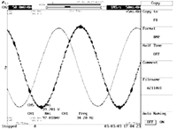
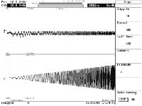
| Fig. 6 output voltage and current Waveform of the medium voltage variable speed drive when the generator load is 90MW |
|
Fig. 7 output voltage and current Waveform of the medium voltage variable speed drive when the motor starts with the medium voltage variable speed drive |
The test results show that the rates of the power saving are respectively 59% with the 72% load and 46% with full load. At the same time, when the motor starts with medium voltage variable speed drive, the starting current rises smoothly and the motor starts very smoothly.
Variable speed drive benefits after reform
1) If operating with full load all the year and 2 medium voltage variable speed drives are used, the estimated annual energy savings will be: 520kW*5,500h=2,860,000 kWh
The electricity cost savings will be at least: 2860000 kWhRMB0.326/kWh=RMB932,000
2) If operating with 72% load all the year and 2 medium voltage variable speed drives are used, the estimated annual energy savings will be: 571kWRMB5,500h=RMB3,140,500 kWh
The electricity cost savings will be at least: 3,140,500 kWhRMB0.326 /kWh=RMB1,024,000
It is obvious that in the case of operating with full load all the year or operating with 72% load all the year and 2 medium voltage variable speed drives produced by Gozuk, the electricity cost savings for the company will be around RMB 1,000,000 for both cases. In addition, since the power factor for medium voltage variable speed drive may be more than 0.95, which is greater than the motor power factor 0.85, it will reduce the reactive power considerably. The soft starting of motors may be performed, thus affection to the motor insulation from high starting surge current may be avoided, maintenance of motors may be easier, service costs may be lower and motor life may be extended greatly.
Conclusion
Medium voltage variable speed drives have obvious energy savings effect. By using Medium voltage variable speed drive, soft starting for motors may be performed and the motor life may be extended. The inlet guide vanes of the induced draft fans will fully open, vibration and wear of the air pipes will be reduced. In brief, the reliable operating performance and good power saving effects of medium voltage variable speed drives have created tremendous economic and social benefits for the company, so it is worth to be recommended and applied.
<- - I have an Opinion - ->

